PCB Board Gallery
Here are the some PCB boards custom designed. All the designs were done through Python-based hardware description language (HDL) PolymorphicBlocks.
Great thanks to Ducky for helping and reviewing the pcb designs.
BALLU
-
BALLU Gen2 PCB Board
Upgraded sensor arrays and Lora sub-G communication compatible
Change from Gen 1
- x2 generic 10 pin FPC connectors for external devices (Lora and contact sensors)
- Pressure/air sensor
- High-end IMU
- Battery sensing
- Power reverse protection
- Enhanced User interface
- 23% less weight
Components
- MCU: ESP32-S3
- Sensors:
- 6-axis IMU (LSM6DSV16XTR)
- BME680 Pressure/Air monitor
- INA219 power sensing
- A31301 3D hall effect sensor (thru expansion cable)
- UI: OLED screen, Directional switch, RGB LED, Red/Blue LED
- Motor: x2 PWM servo
- Power: Lipo, 3.3v reg, Charging circuit, Software Power Switch, Reverse protection
- USB-C: programming, power supply, and charging.
- FPC Connectors: x2 10 pin 0.5mm pitch cables with I2c, SPI, GPIO, gnd, v3v3, vbatt
- 6 layer board
-
BALLU PCB Board
Fully integrated board that includes microprocessor and all sensors in one board
Components
- MCU: ESP32-S3
- Sensors: 9-axis IMU (LSM6DS3TRC and QMC5883L) Voltage sensing.
- UI: OLED screen, Directional switch, Speaker, RGB LED
- Motor: x2 PWM servo
- Power: Lipo, 3.3v reg, Charging circuit, Software Power Switch
- USB-C: programming, power supply, and charging.
- 4 layer board
-
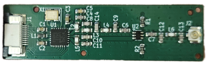
Lora Sx1262 Communication Board
Lora Sx1262 based sub-GHz communication board (915Hz)
Components
- MCU: None (For BALLU Gen2)
- Lora Sx1262
- 2 layer
Acknowledgement
- Special thanks to Ducky for providing reference design and advising
- Special thanks to Eric for placement and routing
-
Lora Communication Daughter Board
STM32G4 based daughter board for BALLU to add Lora Sx1272 based sub-GHz communication board
Components
- MCU: STM32G431 (For BALLU Gen2)
- Programmer pins, status LED
- x2 SPI to the Sx1272 based sub-G communication board
- x1 SPI to BALLU Gen2 board
- 2 layer
MAGPIE
-
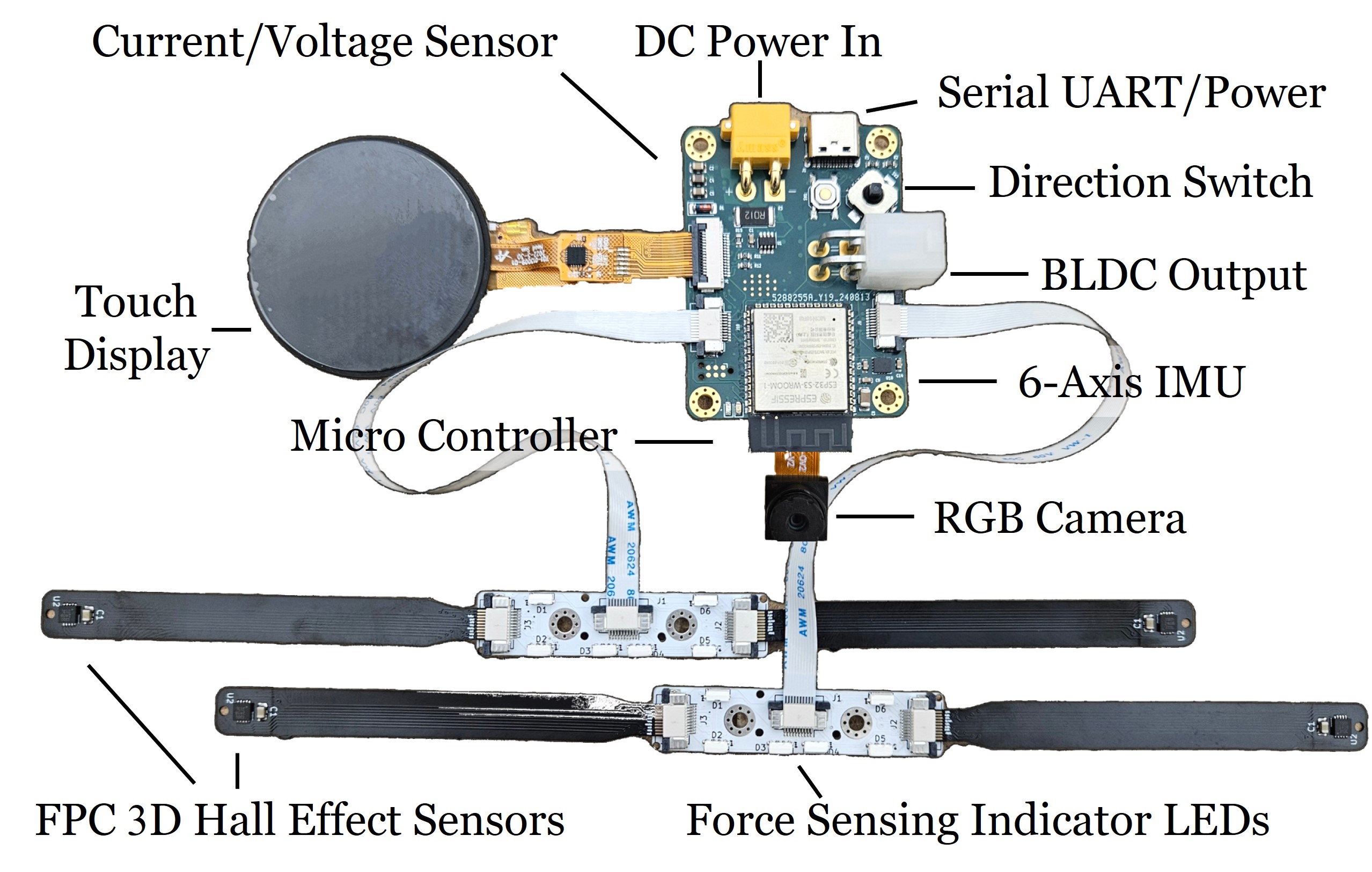
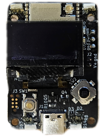
MAGPIE Gen2 PCB Board
Integrated PCB for MAGPIE 3D hall effect based 8-axis force sensing and BLDC driver
Components
- MCU: ESP32-S3
- Power: USB-C & LiPo (7.4–26V) with 4.5V, 3.3V, 3.0V, 2.5V, 1.2V regulation
- Sensors: INA219 power sensing, 6-axis IMU, FPC 3D hall sensor connectors
- Display: Circular TFT touch screen
- Camera: OV2640 FPC module
- Motor: BLDC driver
- UI: Circular color touch screen, RGB LED, directional switch,
- Ports: CAN bus, Wif./pcb/BLE, Dual IO expanders, x2 FPC I2C
- 6 Layer PCB
-
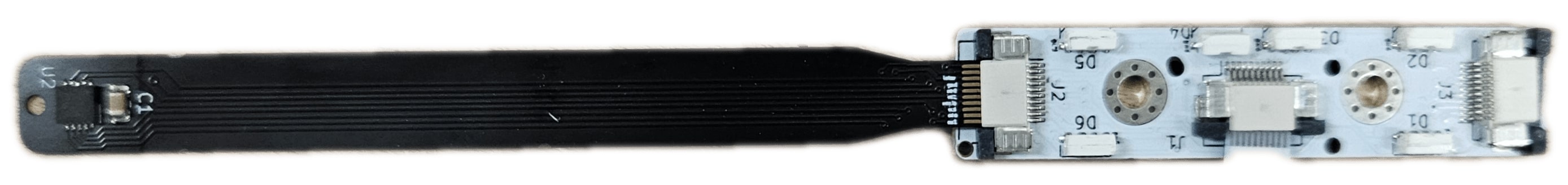
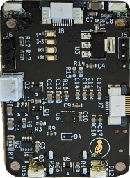
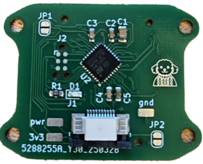
MAGPIE Daughter PCB Board
W/ MAGPIE Sensor Flex PCB
Secondary board for magnetic sensor breakout with contact indicators. 3D hall effect sensor on Flex PCB
Components
- Sensor: upto x2 A31301 through FPC with digital I2C addresser.
- UI: x6 RGB LED Neopixel array for contact indication.
- Connectivity: FPC connectors (1 in, 2 out) Routes I2C, power, and digital signals from FPC.
- Flex PCB with a gold finger, which can be connected to the main board directly
-
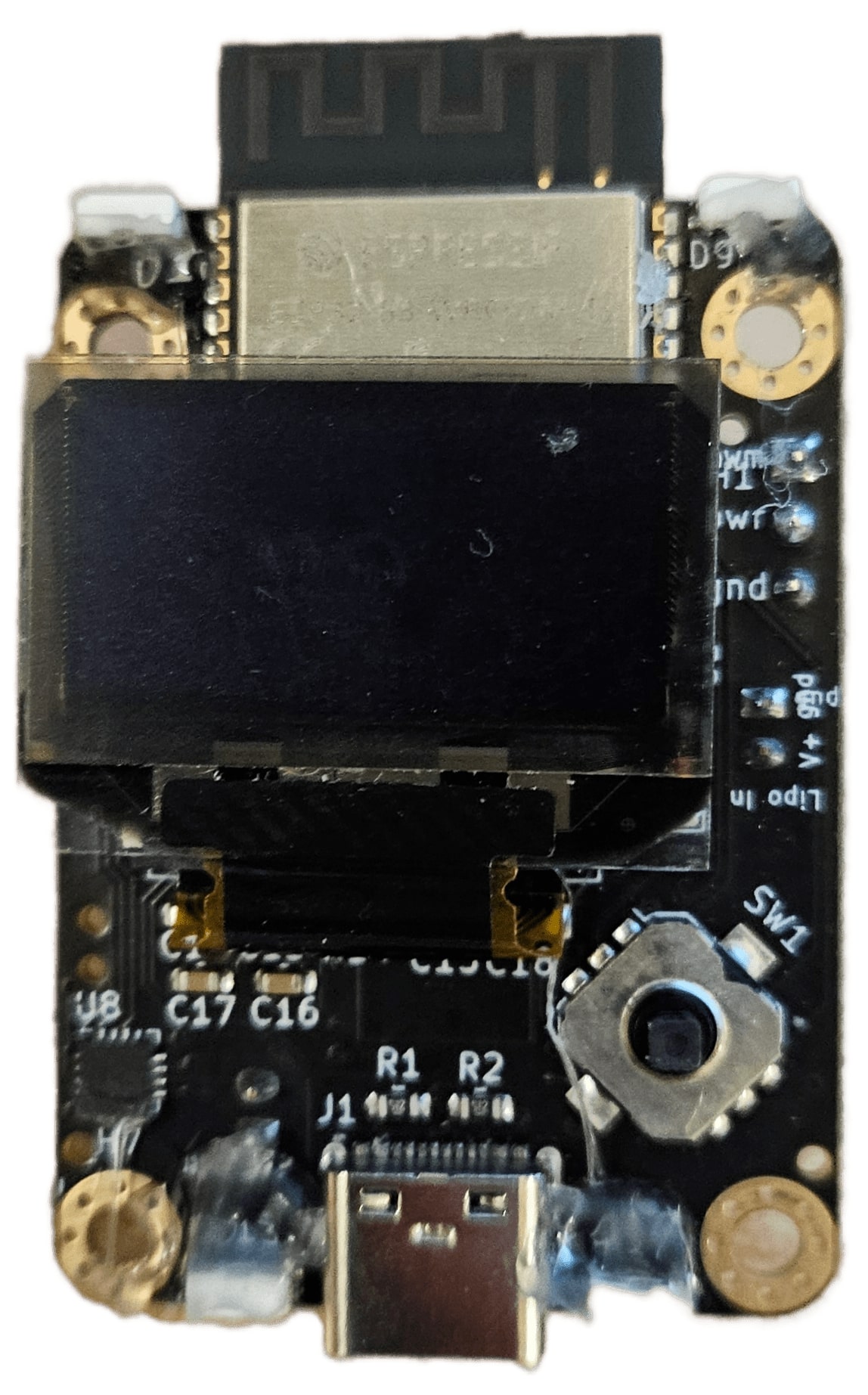
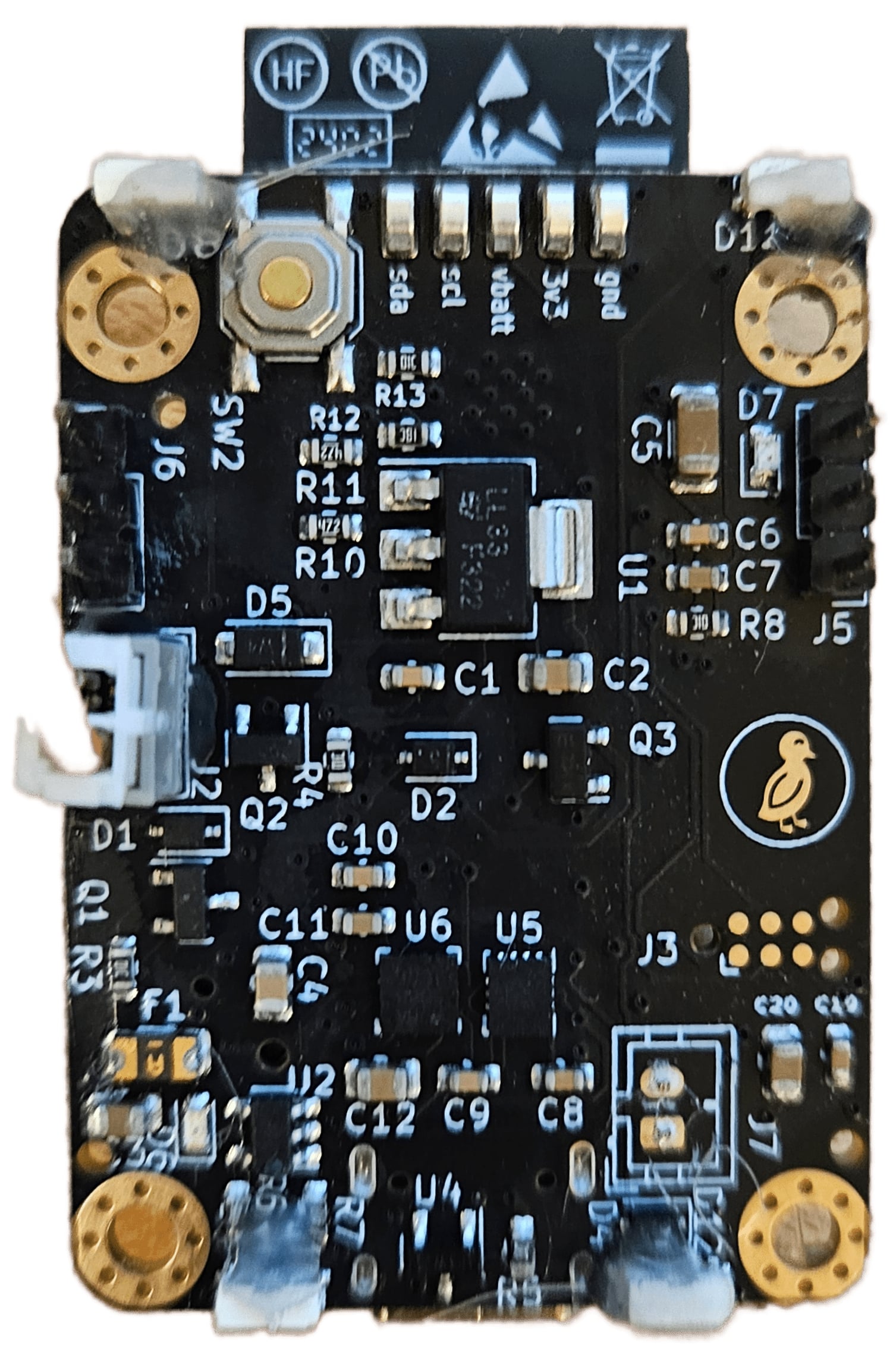
MAGPIE Prototype PCB Board
Prototype MAGPIE PCB board
Components
- MCU: ESP32-S3 for programming, power, and charging via USB-C
- Power: LiPo (7.4–28V) with 4.5V & 3.3V regulation and battery sensing
- Sensors: 9-axis IMU, Qmc5883l magnetometer, and x4 FPC magnetic sensor connectors
- UI: OLED screen, side-firing Neopixel array, and dual debug LEDs (red/blue)
- Controls: Digital directional switch
- Motor: BLDC driver (MCF8316A1VRGFR)
- 4 layer board
Estop
-
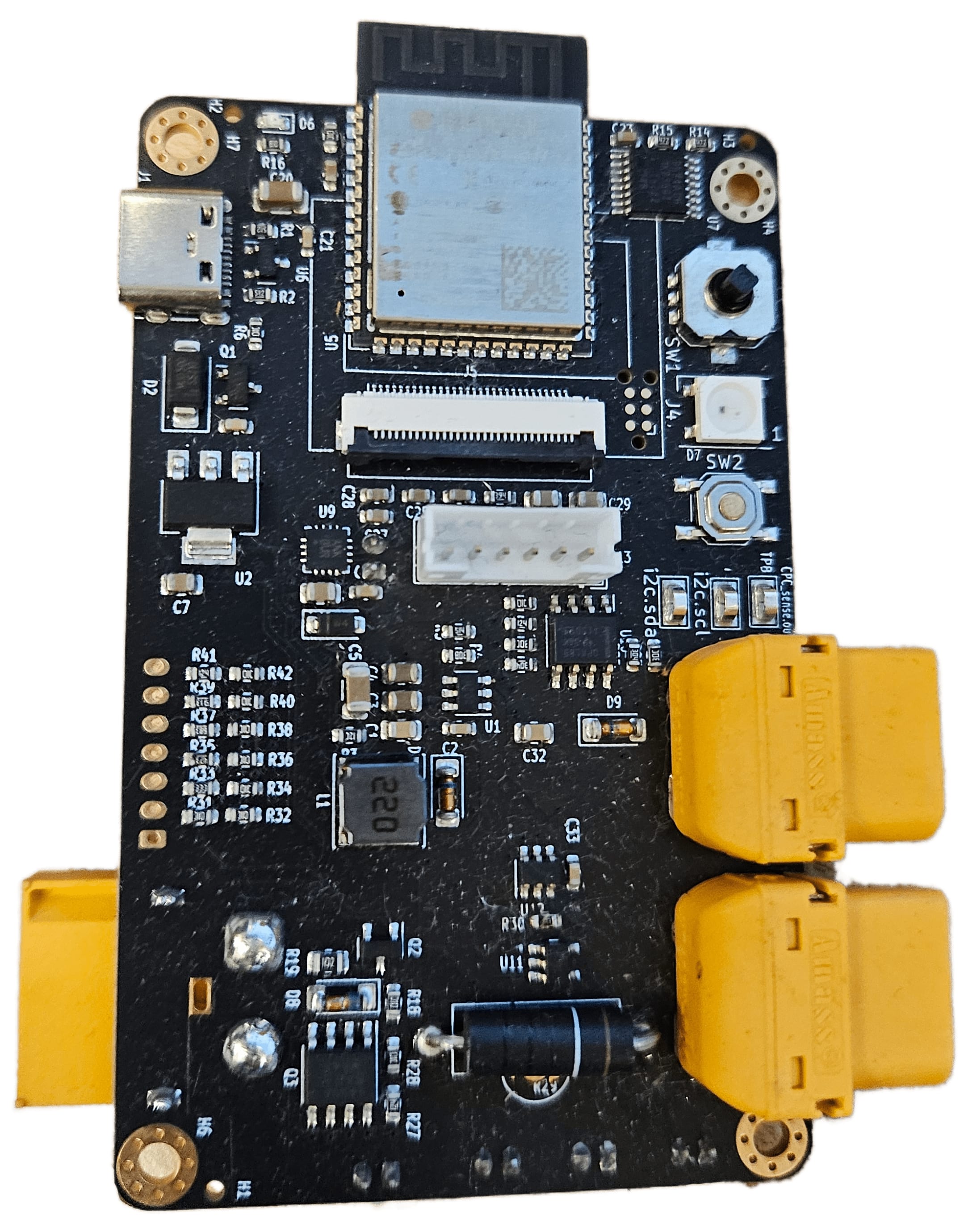
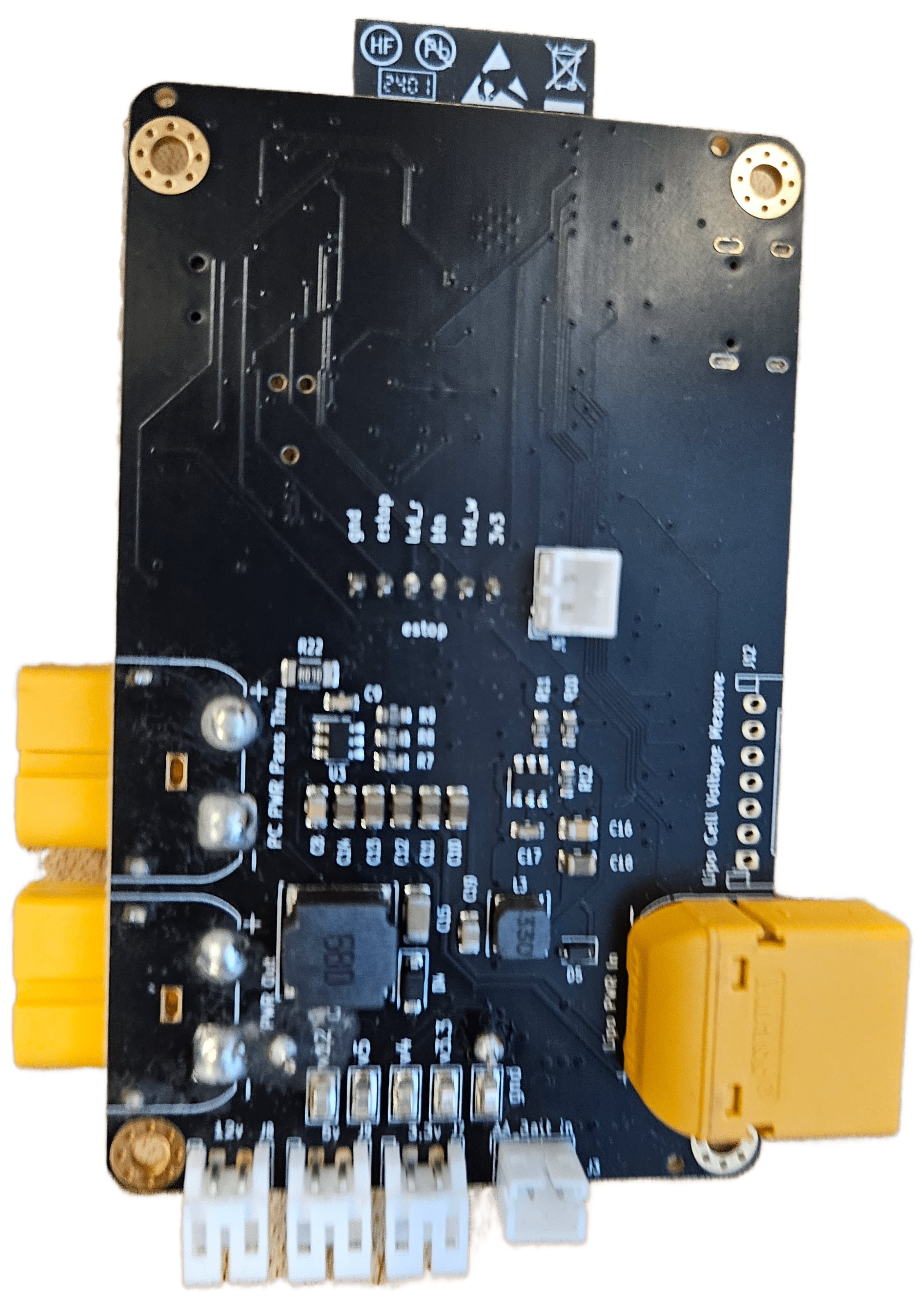
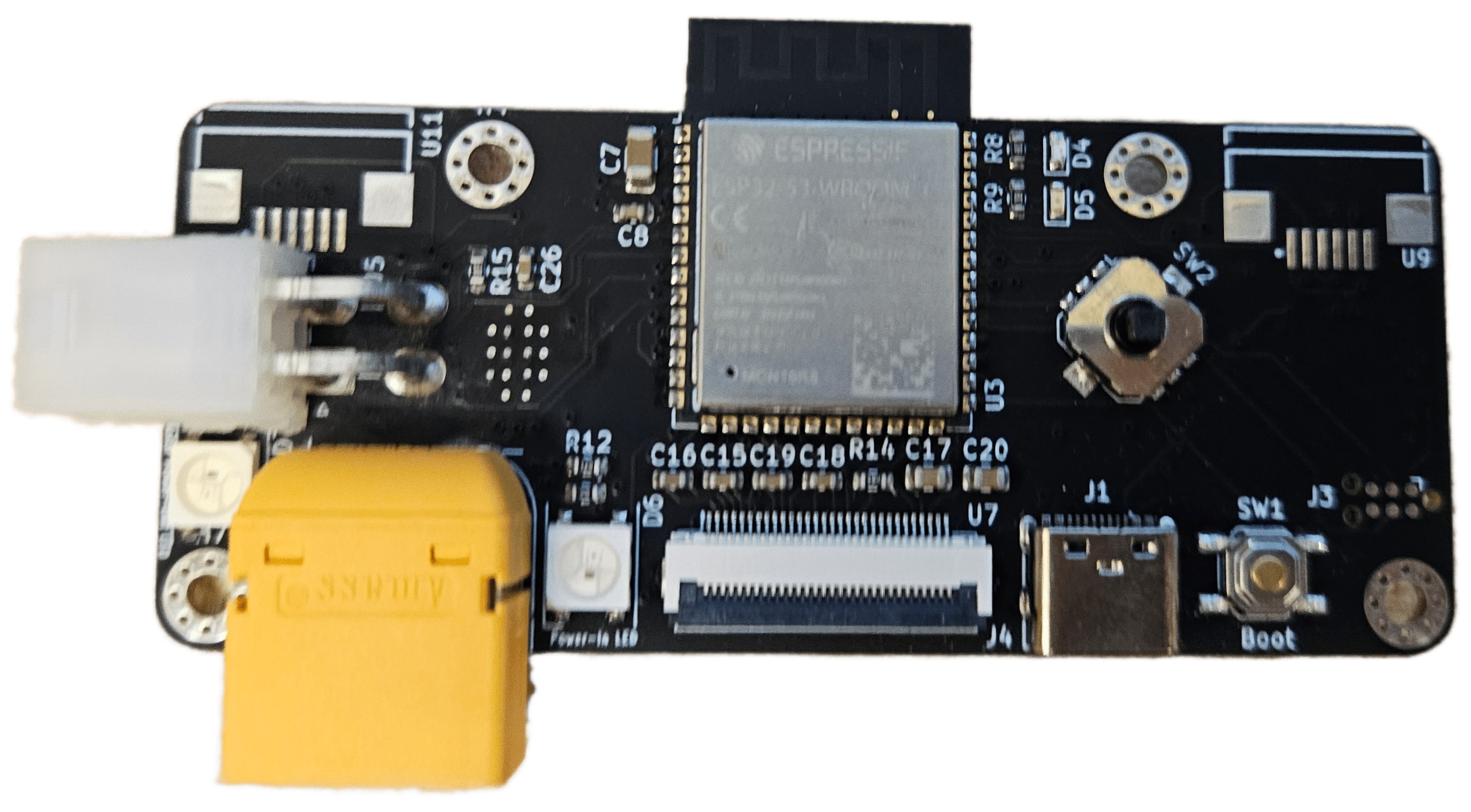
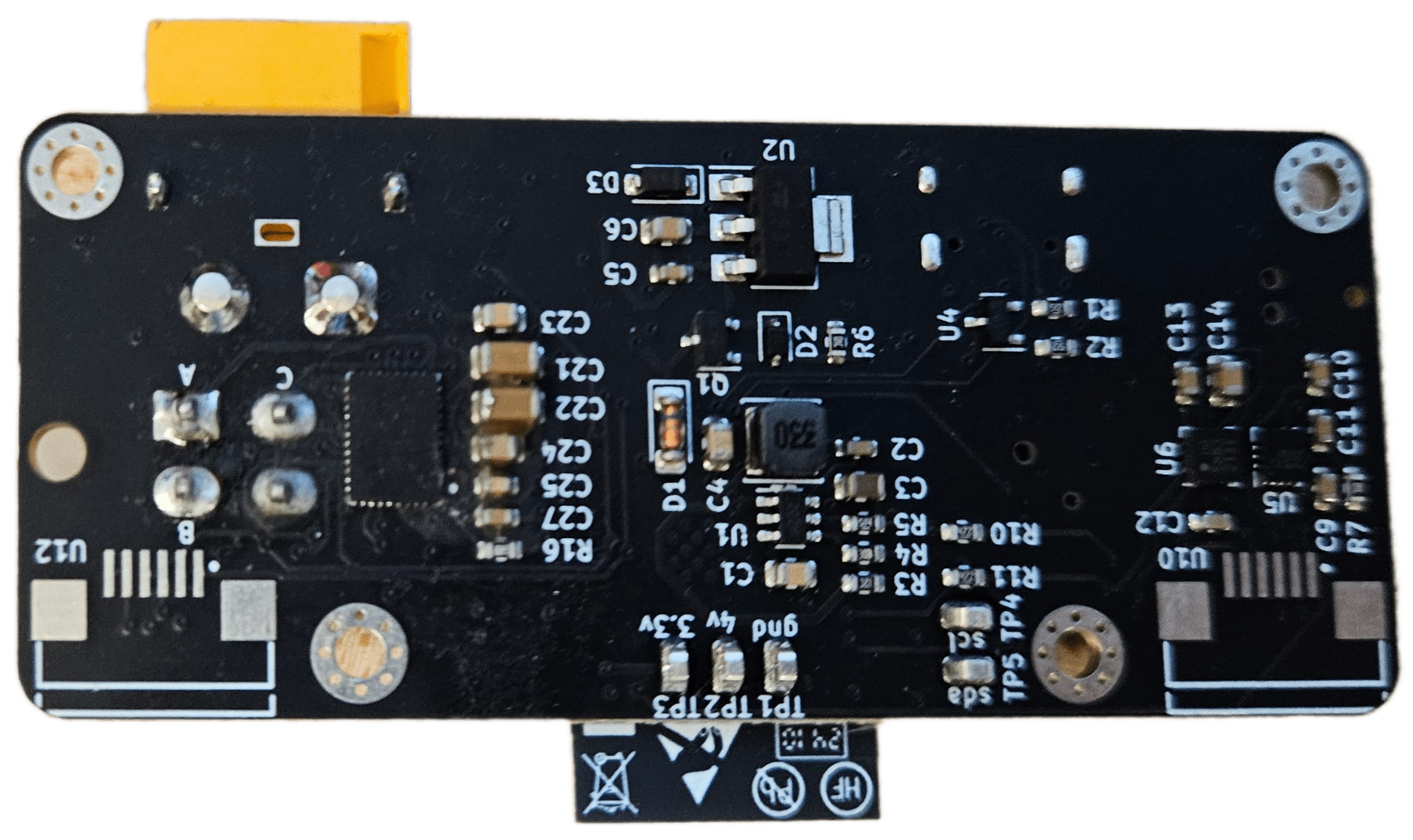
ESTOP PCB Board
Wireless Bluetooth/Wifi E-stop for high-current multi-cell batteries
Components
- MCU: ESP32-S3
- Power: USB-C & LiPo (7.4–28V, up to 20A) with 4.5V, 3.3V, 12V, and 5V regulators
- Battery: High-side MOSFET switch, voltage/current sensing, upto 6-cell monitoring
- UI: OLED display, directional switch, RGB LED, speaker (Max98357a)
- Connectors: JST for 3.3V/12V/5V outputs, XT60 LiPo, and 6-pin E-stop button
PCBbot
-
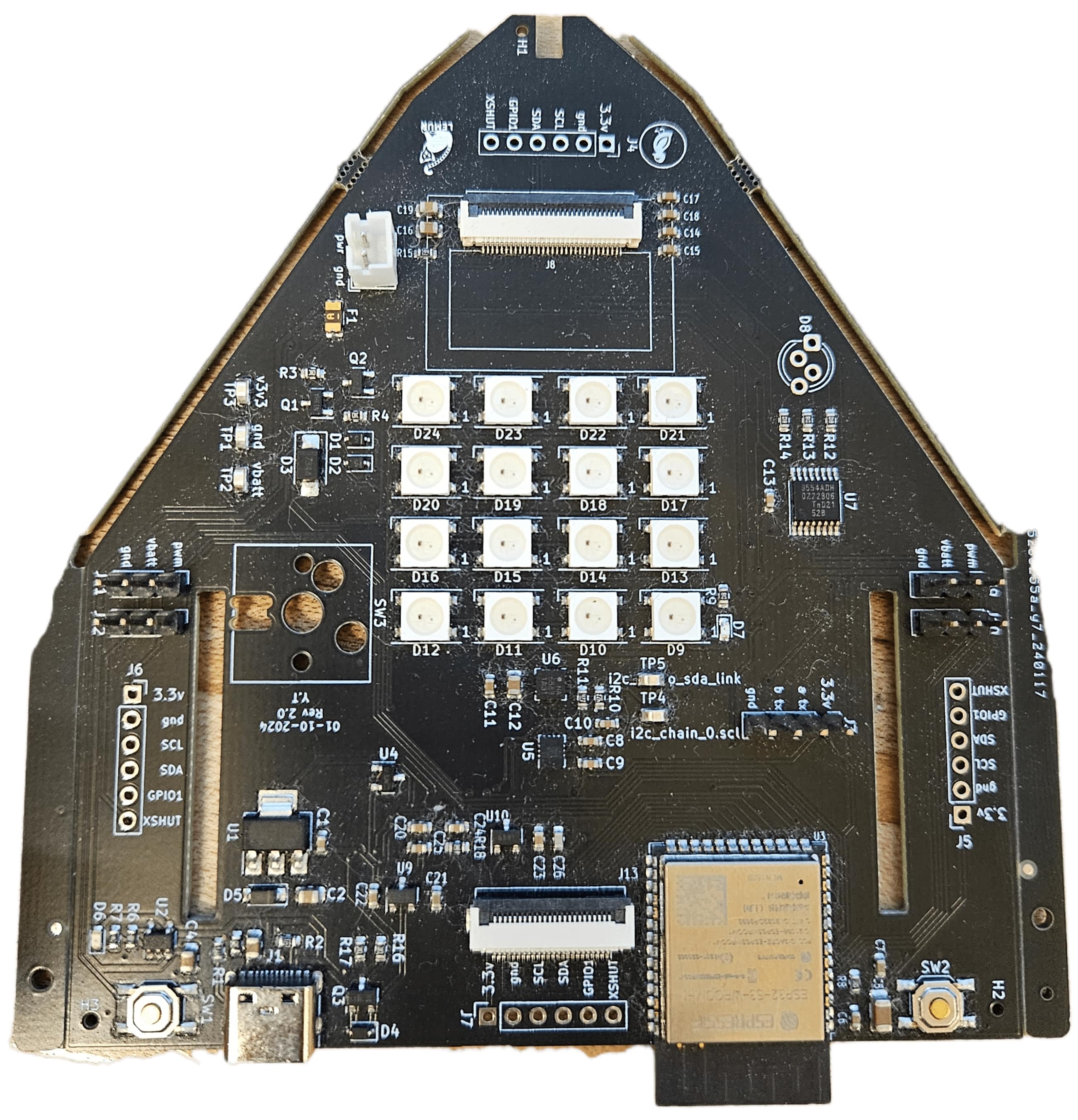
PCBBOT PCB Board
Robot driver board featuring an ESP32-S3 with camera support and student-proofing.
Components
- MCU: ESP32-S3 with USB programming
- Power: USB-C & LiPo (3.7–4.2V) with series fuse, Fet power gate
- Regulation: 3.3V supply with additional 2.5V and 1.2V rails for camera.
- Charging: MCP73831 charger with yellow LED indicator via USB-C.
- Sensors: 4× VL53L0x ToF array, 9-axis IMU.
- UI/I/O: OLED display, debug LED, touch input, and IO expander for ToF control and RGB LED.
- Actuators: 4 PWM connectors for servos
- Camera: OV2640 FPC camera.
Acknowledgement
- Special thanks to Ducky for the design and placement
Sensors and Chargers
-
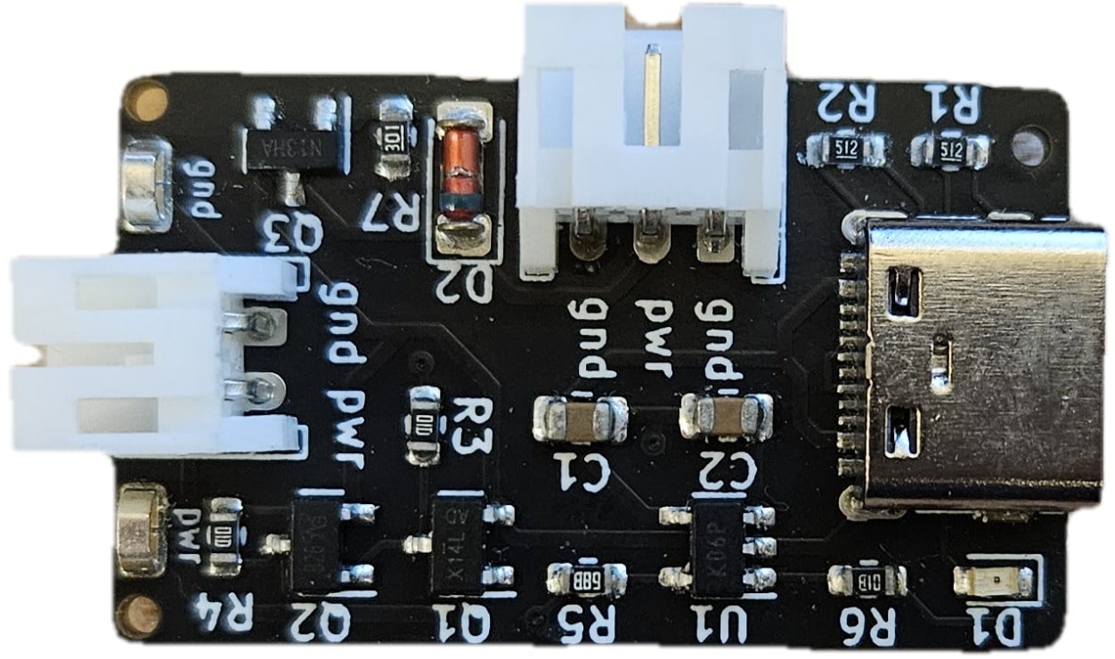
Lipo Charger Board
- Reverse protected 1 Cell Lipo Charger
- Reverse protected load port
-
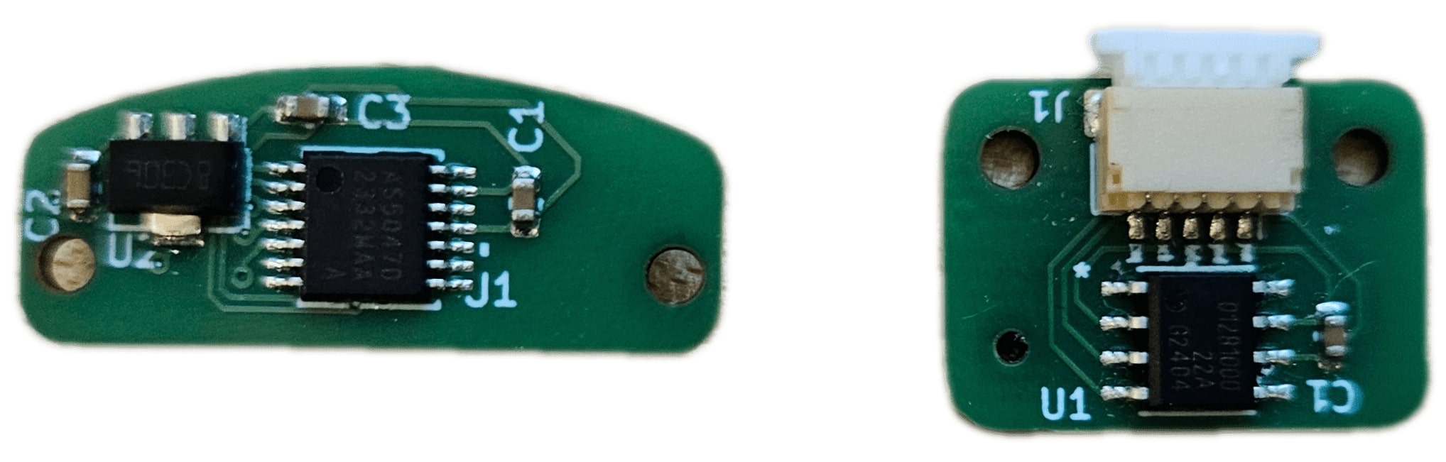
Magnetic Encoder PCB Boards
Ring Magnet encoder PCB Boards compatible with CubeMars and MAB Robotics